Here at Nextech AR, we are proud to announce that we have released our patent pending technology to create optimized 3D meshes that are suitable for 3D and AR applications. With this product, we are now able to scale creating photo realistic, fully textured 3D models from raw CAD models and reference images. This article explains some of the background on the problem and a glimpse of the problems we have solved to make this possible.
Bridging the gap between the science of CAD engineering and the art of 3D modelling
3D CAD is now the most common tool for designing commercial products. Almost all 3D CAD tools work by modelling solids and design operations work with solid operations. For example, to create a hollow cylinder in Fig.1, the CAD operation will involve creating a solid cylinder with radius “R” and subtracting a solid cylinder with radius “r”.
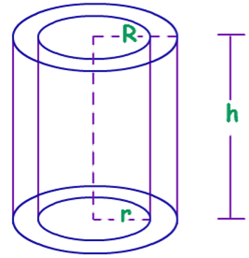
Figure 1 CAD design is based on modelling solids and operations that apply to solid surfaces.
Solid design is appropriate for manufacturing and machining. For example, CAD designs can be converted into files that can be machined using a CNC machine.
CAD and solid design, in general, relies on the concept of parametric surfaces like NURBS (Non-uniform, rational B-splines). A parametric surface is a mapping of the 2D unit square (called the UV plane) to a surface in three dimensions.
The beauty of parametric surfaces, like NURBS, is that the mapping is analytic and hence, in theory, can provide infinitely precise and dense points in the 3D space. In other words, with only a few parameters, one can precisely define and infinitely dense surface. The quantization of the surface points can be done at the last stage and can depend on the accuracy required (or tolerated) by the end machinery that consumes the CAD design.
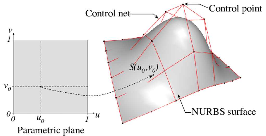
Figure 2 A parametric surface (like NURBS) maps a part of the 2D space (or the UV space) to a surface in the 3D physical space.
Computer Generated Imagery Requires 3D Meshes
While this is highly desirable for manufacturing design, it poses a problem when the same 3D CAD drawings are going to be used for computer generated imagery (CGI).
3D CGI is almost exclusively based on the concept of tessellated surfaces (that are hollow and not solid). In fact, there’s no concept of a solid in most CGI design tools; everything is a surface. Furthermore, rendering engines that render 3D CGI objects require tessellated meshes for optimization of ray-casting and shading. That is how almost any 3D modelling and rendering software works (e.g., Blender, Maya, 3D MAX Studio, etc.). Therefore, to be able to use a CAD design for CGI purposes (e.g., to let customers view the product in 3D on their mobile or desktop websites), a 3D CAD model needs to be translated into a polygon mesh. We call this overall operation CAD to POLY or C2P.
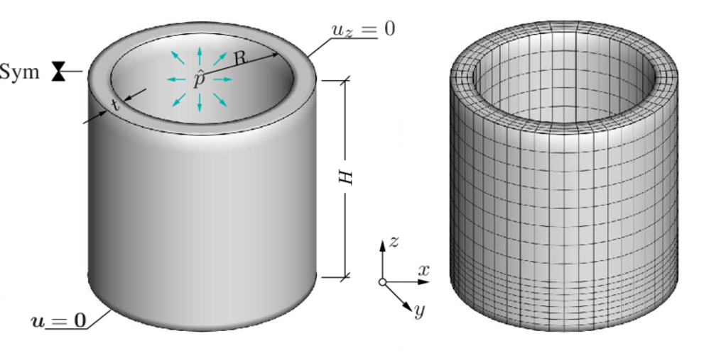
Figure 3 Solids have to be tessellated to turn into surfaces that are useful for 3D CGI
Most CAD software (like AutoCAD or FreeCAD) are able to natively create mesh surfaces from the CAD files. This process is called tessellation. If the polygons are triangle (which is the most common form of tessellation), the process is called triangulation. If the polygons are quads, the process is called quadangulation.
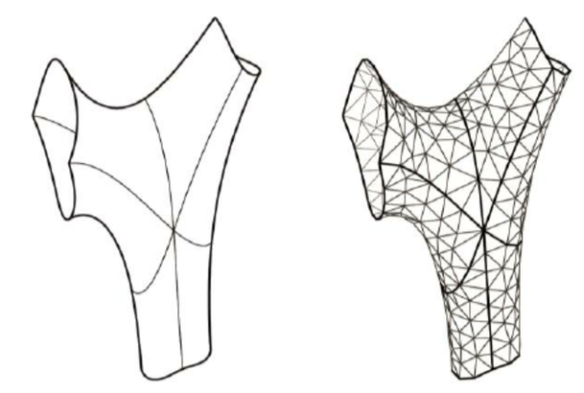
Figure 4 Tessellation of faces into triangles.
Quad vs. Triangle Meshes
For reasons that are beyond the scope of this post, a quad mesh is greatly preferred over a triangular mesh. However, quad tessellation is much harder in practice and most packages just return a triangular mesh. The process of taking a triangular mesh and creating a (mostly quad) mesh from it is called quad-retopology. There are commercial packages for quad retopology, but it is still an art and requires experience and extensive try-and-error.
Figure 5 Quad topologies are more desirable for mesh modelling as they allow better control for selecting loops, etc.
UV-Unwrapping and Texturing
Unlike a CAD design, 3D CGI requires the model to be textured so it looks a realistic product. Most CAD software lets you to assign simple colors to CAD parts, but that’s far from what’s required for modern CGI.
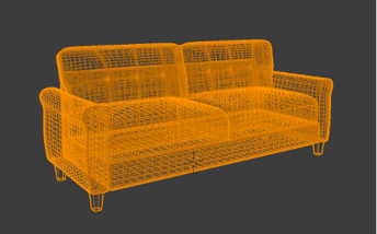
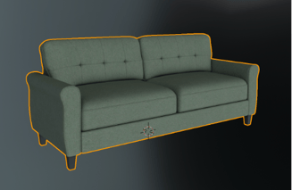
Figure 6 A non-textured mesh vs. a textured mesh
The most common modern texturing technology is called Physics Based Rendering or PBR. It relies on the rendering engine simulating or approximating the actual physical process of light interacting with the surfaces (or faces) of the meshes in the model. PBR requires a number of “maps” to indicate the color, transparency, reflection, etc. for each of the vertices in the mesh. These are called PBR maps.
One major problem in 3D CGI is how to map these flat 2D image maps to the 3D surface of a mesh. This process is called UV-Unwrapping because it takes a 3D surface in XYZ space, and unwraps it onto a 2D space, or UV. As basic Topology tells us, this unwrapping can cause a “tear” and require unavoidable seams in many cases (think of trying gift-wrap a soccer ball). There’s a large body of literature on how to minimize the stretch or make seams less visible. UV-Unwrapping is one of the major pain points for 3D designers. A CAD engineer does not need to worry about UV maps when designing solids, but a 3D artist needs to make sure the unwrapping is effective for the end model to render with high quality in a 3D rendering engine.
Bridging Engineering and Art Gap with CAD to POLY
Since CAD and Mesh design are two fundamentally separate disciplines (one is engineering, the other is art), this destructive hand-off has seemed inevitable. The engineering or “industrial design” department creates a CAD for manufacturing, the “marketing” and “web” department will receive a tessellated mesh that is the default output of the original CAD software.
This mesh is often essentially useless for the CGI artists. Here are the main reasons:
- The meshes are often very dense. Many times, we have seen ones with 10M faces. In theory a mesh like that can be decimated. Current real-time 3D renderers require < 100K faces in a model. A 100X decimation on a large mesh like that will inevitably distort it heavily and will make the mesh unusable,
- The mesh it is usually lumped at a high level, i.e., it is usually one single connected mesh (that’s the default in all CAD software). The problem is that texturing such lump of vertices is hard. Firstly, the UV-Unwrapping is next to impossible. But more importantly, almost always different parts of the mesh require a different texture or material (think of a chair with black legs and brown seat). When the meshes are all joined, it can be very hard to separate the parts, to UV-Unwrap them individually and to assign textures or materials to individual parts.
- CAD models often contain all the details of the product that will not be visible to a user of a CGI. Think of a car, for example. If the goal of CGI is to render the car in a 3D environment for an advertisement, all the details of the engine will be invisible to everyone but create massive inefficiencies for the renderer.
We have solved all these problems by digging deep into how CAD models are parametrized and bridged the gap to turn those surfaces into optimized tessellated meshes automatically.
Unlike native operations in CAD, the process of tessellation of a parametric surface is destructive. In other words, tessellation (or quantization of any kind) will inevitably lose some of the information contained in the original parametric surface. By the time the artist receives a tessellated mesh, much of the original information about the composition and assembly of the CAD file are lost. The parts may have been merged and hard to segment out, etc. This doesn’t have to be the case. Our tech bridges this gap between 3D CAD design (i.e., engineering) and 3D Mesh modelling (i.e., art).
A corner stone of our product is what we call “Tessellation from First Principles” or TFFP. The idea is that to keep and use as much information that was directly encoded in the parametric surfaces of a CAD model for as long as possible and use that to inform the creation and unwrapping of the 3D meshes.
Putting it all together, our newly released product is a huge step towards bridging the gap between the world of industrial design and the emerging metaverse.
To get started to turn your CAD files into beautiful 3D models that can be used for 3D visualization, AR and virtual photography, please contact us.